> Details
> Details
Meshes
If a mesh is intersected by the slicing plane, XSLICE will dismantle it and turn the mesh into its components (3D faces, lines, and points). After slicing, all the mesh components on the desired side of the plane are reassembled to a single polyface mesh if their total number is not greater than 8191. Otherwise the faces, lines, and points will remain individual objects. In case you have chosen "both sides", two polyface meshes will be created on either side of the slicing plane if the number of components does not exceed 8191 on either side.
Assumed that the aforementioned number of components (per side) is greater than 8191 but not greater than 32767, then you still have a chance: Try to reassemble the components by means of the SEW function. You will succeed on condition that the faces are well-positioned (see details about limitations of the SEW function) but it may consume much time. Therefore XSLICE does not start such a try automatically.
During the dismantling process a polyface mesh is losing its invisible line and point components (rarely used); but faces with invisible edges are maintained. New edges generated by slicing (lying on the slicing plane) are always made visible.
XSLICE turns polygon meshes into polyface meshes. This has an effect on the particular use of surface fit meshes: After applying the XSLICE function you cannot activate or deactivate surface fitting, and you cannot refine meshes by setting U and V values (cf. AutoCAD 14 "ddmodify" command, AutoCAD 2000 "properties" command, AutoCAD "splframe", "surfu", and "surfv" system variables).
The Gouraud shading mode of AutoCAD 2000 gives a very smooth appearance to polygon meshes. Polyface meshes with smooth edges are obtained by rendering only.
Quadrangular 3D faces are always considered as compounds of two triangles touching one another along the "diagonal" from the second to the fourth corner. Sometimes the graphics screen output produced by AutoCAD may differ from this rule (after hiding lines or shading) depending on the current viewpoint.
This should be taken into account before creating faces and meshes - especially concave quadrangles, or quadrangles with intersecting non-successive edges ("butterflies"), or non-planar faces. The latter often occur as parts of polygon meshes created by means of the "rulesurf" command.
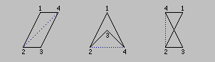
The drawing shows a convex quadrangle, a concave quadrangle, and a quadrangle with intersecting edges.
Sometimes slicing a quadrangular face leaves a pentangular or hexangular rest. AutoCAD and IntelliCAD allow 3D faces with four corners at most; that is why in such cases the new face is combined by two 3D faces. The shared edge is made invisible.

Unfortunately, IntelliCAD and AutoCAD 14 and previous releases use the other diagonal to divide a face from the first to the third corner.
> Details
> Details